HPK taruh disini
Hello guys, i want to sharing
about my simulation project. This is about microcontroller with LDR sensor and
LED. I will create this automatic lighting project with Arduino and Proteus 8. You
must remember that this is just a simulation project. If you want to realize it
, it is much better. It’s so simple and easy , you just need this components below :
1. Light Dependent Resistor (LDR)
Light Dependent Resistors (LDRs) also known as Photoresistors, or photocells, are low-cost variable resistors where the resistance changes depending on the amount of light hitting its surface. In dark environments the resistance is high; in light environments the resistance is lower. Due to the imprecise nature of photoresistors, they are unsuitable for measuring exact levels of light but are capable of detecting changes. They can be used to respond to events such as the transition from daytime to night-time (and vice versa) for home automation and gardening applications, and are often used to control street lighting. In this project, Arduino Uno will controlling it with ADC pin and Digital Output pin.
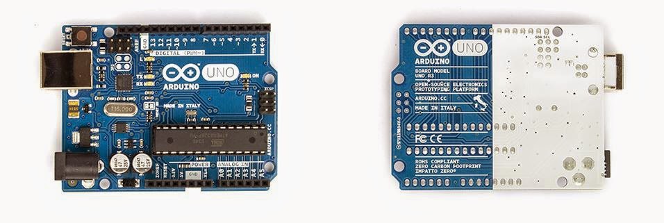
2. Arduino
Uno
“The Arduino Uno is a microcontroller board based on
the ATmega328 .It has 14 digital input/output pins (of which 6 can be
used as PWM outputs), 6 analog inputs, a 16 MHz ceramic resonator, a
USB connection, a power jack, an ICSP header, and a reset button. It contains
everything needed to support the microcontroller; simply connect it to a
computer with a USB cable or power it with a AC-to-DC adapter or battery to get
started.” For
more information, you can click Here.
3. Liquid Crystal Display (LCD)
Liquid Crystal Displays (LCDs) offer several advantages over traditional cathode-ray
tube displays that make them ideal for several applications. Of course, LCDs
are flat, and they use only a fraction of the power required by CRTs. They are
easier to read and more pleasant to work with for long periods of time than
most ordinary video monitors. There are several tradeoffs as well, such as
limited view angle, brightness, and contrast, not to mention high manufacturing
cost. As research continues, these limitations are slowly becoming less
significant. In this project, LCD will be used for give your information about
ADC Value from LDR.
4. Light Emitting
Diode
The LED is a light
source which uses semiconductors and electroluminescence to create light. Currently
the LED lamp is popular due to it's efficiency and many believe it is a 'new'
technology. It common uses: indication lights on devices, small and large
lamps, traffic lights, large video screens, signs, street lighting(although
this is still not widespread). LEDs create light by electroluminescence in a
semiconductor material. Electroluminescence is the phenomenon of a material
emitting light when electric current or an electric field is passed through it
- this happens when electrons are sent through the material and fill electron
holes. An electron hole exists where an atom lacks electrons (negatively
charged) and therefore has a positive charge. Semiconductor materials like
germanium or silicon can be "doped" to create and control the number
of electron holes. Doping is the adding of other elements to the semiconductor
material to change its properties. By doping a semiconductor you can make two
separate types of semiconductors in the same crystal. The boundary between the
two types is called a p-n junction. The junction only allows current to pass
through it one way, this is why they are used as diodes. LEDs are made using
p-n junctions. As electrons pass through one crystal to the other they fill
electron holes. They emit photons (light).
A resistor is a component
that resists the flow of electricity. This flow of electricity is called current. Each resistor has a value that tells how
strongly it resists current flow. This
resistance value is called the ohm, and the sign for the ohm is the Greek
letter omega: Ω. (Later on you will see
the symbol kΩ, meaning kilo-ohm, which is one thousand ohms.) In electronic
circuits, resistors play an important role to limit the current and provide only
the required biasing to the vital active parts like the transistors .
To build this project, you just necessary Proteus 8
Professional, Arduino Software and Library. The Proteus 8 Professional and
Arduino Library have to connected, because the program of Arduino will be
upload in Proteus 8 Professional, so Arduino can excecute the program to
controll this simulation. To connected them, you can visit this information.
Then, you can starting to build this project.
1. Open
your Proteus
8 Professional and create this circuit.
2. Open
Your Arduino Software and create this code in here
 |
| Coding for describe the variable |
 |
| Coding for arduino first output condition |
 |
| Coding for LED lights up |


