HPK taruh disini
Roller Blind is a type of window covering. These are a usually stiffened polyester, mounted on a metal pole and operated with a side chain or spring mechanism. Lower cost and ready made blinds often come with a PVC pole. These days, roller blinds have been modified with a motor, so with the motorized roller blind, the side chain is not needed for opening or closing the blind, motor will rotate clockwise when opening the blind, and counter clockwise when closing the blind. But, most of motorized roller blind are semi automatic. We still have to control with remote control. So, this article will explain how to design a automatic roller blind.
Automatic roller blind can be light dependent , so the blind will be open or close if there is sunlight or there isn’t sunlight. Another method is with a scheduling, so we will set what time the blind is opened and what time the blind is closed. Because in this article, we will make a simulation so, the automatic roller blind that will be designed is a scheduling one
Automatic roller blind can be light dependent , so the blind will be open or close if there is sunlight or there isn’t sunlight. Another method is with a scheduling, so we will set what time the blind is opened and what time the blind is closed. Because in this article, we will make a simulation so, the automatic roller blind that will be designed is a scheduling one

Roller Blind

Mechanism of Roller Blind
In this project, we will learn how to drive DC motor using microcontroller and learn to generate clock from microcontroller. The clock will be used for scheduling the automatic blind. The clock will be displayed at 16x2 LCD display.
Hardware requirement and Schematic:
In this design, we will require:
- · 1 DC Tubular motor for blind
- · 1 Arduino Uno R3
- · 5 pushbutton
- · 1 Pot 10k
- · 5 Resistor 1k
- · 1 Dual H-bridge Motor Driver - L293D IC
- · 16 x 2 LCD Display
The Schematic for this project can be seen below:

H-Bridge Motor Driver
 The DC tubular motor for blind is assumed as a normal DC Motor in simulation. So we need a motor driver to drive the motor. Motor driver is basically a current amplifier which takes a low-current signal from the microcontroller and gives out a proportionally higher current signal which can control and drive a motor. In most cases, a transistor can act as a switch and perform this task which drives the motor in a single direction.
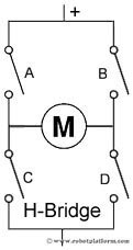
Turning a motor ON and OFF requires only one switch to control a single motor in a single direction. What if you want your motor to reverse its direction? The simple answer is to reverse its polarity. This can be achieved by using four switches that are arranged in an intelligent manner such that the circuit not only drives the motor, but also controls its direction. Out of many, one of the most common and clever design is a H-bridge circuit where transistors are arranged in a shape that resembles the English alphabet "H".
As you can see in the image, the circuit has four switches A, B, C and D. Turning these switches ON and OFF can drive a motor in different ways.
- · Turning on Switches A and D makes the motor rotate clockwise
- · Turning on Switches B and C makes the motor rotate anti-clockwise
- · Turning on Switches A and B will stop the motor (Brakes)
- · Turning off all the switches gives the motor a free wheel drive
- · Lastly turning on A & C at the same time or B & D at the same time shorts your entire circuit. So, do not attempt this.
 H-bridges can be built from scratch using relays, mosfets, field effect transistors (FET), bi-polar junction transistors (BJT), etc. But if your current requirement is not too high and all you need is a single package which does the job of driving a small DC motor in two directions, then all you need is a L293D IC. This single inexpensive package can interface not one, but two DC motors. L293, L293B and few other versions also does the same job, but pick the L293D version as this one has an inbuilt flyback diode which protects the driving transistors from voltage spikes that occur when the motor coil is turned off.
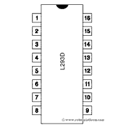
L293D IC generally comes as a standard 16-pin DIP (dual-in line package). This motor driver IC can simultaneously control two small motors in either direction; forward and reverse with just 4 microcontroller pins (if you do not use enable pins). Some of the features (and drawbacks) of this IC are:
The circuit shown to the right is the most basic implementation of L293D IC. There are 16 pins sticking out of this IC and we have to understand the functionality of each pin before implementing this in a circuit
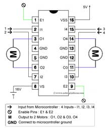
- Pin1 and Pin9 are "Enable" pins. They should be connected to +5V for the drivers to function. If they pulled low (GND), then the outputs will be turned off regardless of the input states, stopping the motors. If you have two spare pins in your microcontroller, connect these pins to the microcontroller, or just connect them to regulated positive 5 Volts.
- Pin4, Pin5, Pin12 and Pin13 are ground pins which should ideally be connected to microcontroller's ground.
- Pin2, Pin7, Pin10 and Pin15 are logic input pins. These are control pins which should be connected to microcontroller pins. Pin2 and Pin7 control the first motor (left); Pin10 and Pin15 control the second motor(right).
- Pin3, Pin6, Pin11, and Pin14 are output pins. Tie Pin3 and Pin6 to the first motor, Pin11 and Pin14 to second motor
- Pin16 powers the IC and it should be connected to regulated +5Volts
- Pin8 powers the two motors and should be connected to positive lead of a secondary battery. As per the datasheet, supply voltage can be as high as 36 volts.
Truth table
Suppose you need to control the left motor which is connected to Pin3 (O1) and Pin6 (O2). As mentioned above, we require three pins to control this motor - Pin1 (E1), Pin2 (I1) and Pin7 (I2). Here is the truth table representing the functionality of this motor driver.
Pin 1
|
Pin 2
|
Pin 7
|
Function
|
High
|
High
|
Low
|
Turn Anti-clockwise (Reverse)
|
High
|
Low
|
High
|
Turn clockwise (Forward)
|
High
|
High
|
High
|
Stop
|
High
|
Low
|
Low
|
Stop
|
Low
|
X
|
X
|
Stop
|
PWM
PWM is one of method used for speed control of DC motor.Pulse Width Modulation, or PWM, is atechnique for getting analog results with digital means. Digital control is used to create a square wave, a signal switched between on and off. This on-off pattern can simulate voltages in between full on and off by changing the portion of the time the signal spends on versus the time that the signal spends off. The duration of "on time" is called the pulse width. To get varying analog values, you change, or modulate, that pulse width. Average voltage of PWM is applied to dc motor. So, to control the speed, we should set PWM value.
In the graphic below, the green lines represent a regular time period. This duration or period is the inverse of the PWM frequency in Arduino. With Arduino's PWM frequency at about 500Hz, the green lines would measure 2 milliseconds each. A call to analogWrite() is on a scale of 0 - 255, such that analogWrite(255) requests a 100% duty cycle (always on), and analogWrite(127) is a 50% duty cycle (on half the time) for example. The PWM output of Arduino will be connected to pin1 of L293D, so the output for DC motor is in 0-12 Volt range, the range is not in 0-5 volts anymore.

Arduino Uno R3
The Arduino Uno is a microcontroller board based on the ATmega328 (datasheet). It has 14 digital input/output pins (of which 6 can be used as PWM outputs), 6 analog inputs, a 16 MHz ceramic resonator, a USB connection, a power jack, an ICSP header, and a reset button. It contains everything needed to support the microcontroller; simply connect it to a computer with a USB cable or power it with a AC-to-DC adapter or battery to get started.

16x2 LCD Display is used for displaying clock in hh:mm:ss format. We just use the first row for displaying the clock. We want the clock should show the real time, so the pushbutton is used for setting the clock. We need 3 pushbutton, the first one is for setting hour, the second is for setting first digit of minute and the third is for setting second digit of minute. In schematic,Button Hour is the first pushbutton, Button Minute 1st digit is the second pushbutton, and Button Minute 2nd digit is the third pushbutton.
Another 2 pushbutton are functioned as sign that the blind is opened or closed and used to control the motor. One of pushbutton (SW1 in schematic) is located on Top, below the Roller Tube and the other one (SW2 in schematic) is located on Bottom near Bottom Bar End Cup of Blind when the blind is unrolled. So when the blind is rolled, if SW1 is touched by bottom cap the motor will stop, and when the blind is unrolled, if SW2 is touched by bottom cap, the motor will stop. So the SW1 and SW2 are the signed that blind is rolled or unrolled. SW1 and SW2 send signal to stop motor. We used pushbutton, because it is easier to simulate. We can used LED and photodiode as sensor to give open or closed condition when implementing this design.
Software design
Before designing the software, we should make the algorithm for the software. The algorithm for this project can be seen below.

In this design, the automatic roller blind will be open at 6 o’clock and closed 18 o’clock. So, when it’s 6 o’clock, motor will roll the blind automaticly and when it’s 18 o’clock the motor will unrolled blind automaticly. That’s why we should set the clock using the button to get a real time execution.
Here’s the code. Use Arduino IDE to program the Arduino Uno.
Codes Below are used for initialize pin and including LCD library in this project.

Codes below are used for set the pin as input or output, and set 16x2 LCD display.

Codes below are used as constructor for drive motor using IC L293d H-Bridge

Codes below are used for generating clock.

Codes below are used for displaying the clock at LCD display

Codes below are used for button state change detection, and it used as counter to set the clock.

Codes below are the code that will be execute every time. All construction above will be execute in void loop(). Boolean type of Open will be used for showing that blind is open or closed.

SIMULATION
Video Simulation :
Simulation with Proteus 8: Click Here to Download
